SCinet Nixie Marquee

This twenty character Nixie marquee was built as a network data monitor for SCinet committee of the SC 2004 conference. The original conception was as a “bit-o-meter” to display a live running counter of the number of bits passing through the network to and from the wide area. (The SCinet network for SC 2004 boasted sixteen OC-192 and one OC-768 circuits for a total wide area connectivity of 200 Gb/s. If we ran full out for the entire duration and kept the count in bits this could possibly consume 16 digits.) The B-7971 tubes were the only readily available tubes large enough for the task so we went from simply having a “bit-o-meter” to an alphanumeric display.
Technical Details
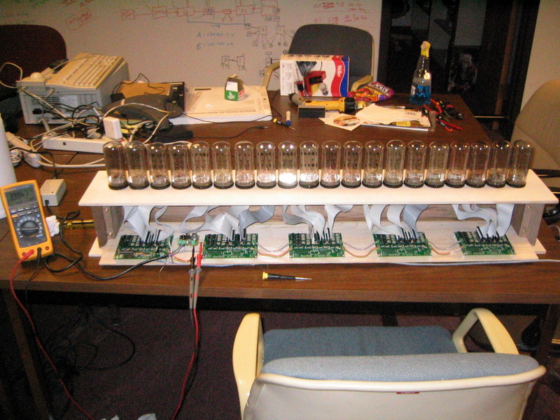
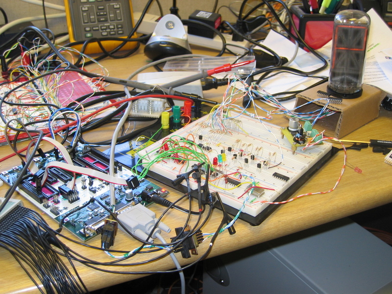
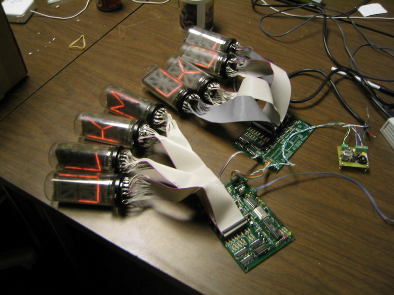
The display uses 20 Burroughs B-7971 Alphanumeric Nixie Tubes driven by custom hardware. The hardware consists of a custom two layer PCB. There are five of these boards in the unit, one of which has the microcontroller section populated. The four other boards are connected in a daisy chain to the board with the microcontroller. The tubes are multiplexed in five banks of four. The whole system is driven by a single Atmel AVR Mega8 microcontroller. The firmware was developed using the AVR port of the GNU toolchain (AVR GCC).
The marquee is updated via a serial connection over Bluetooth. There is a small Python script included in the firmware zip file which can be used to send a new message to the sign.
During operation the marquee consumes approximately 500 mA. Initially some of the tubes were slow to strike but this problem has lessened over time and most likely has something to do with how long the tubes have been in storage.
Files
Improvements
There are several areas which could be improved, primarily in the firmware.
- Currently the firmware doesn’t support scrolling, this would make several other things much easier. (There is some code that does scrolling but it needs to be reworked).
Acknowledgements
The NEONIXIE-L list provided inspiration and inexhaustible information. Thanks to Nick de Smith who’s Nixie HV Switching PSU was used to provide the HV for this display (with some part substitutions). The design of this board owes much to the GeekKlok by Raymond Weisling.
Photos
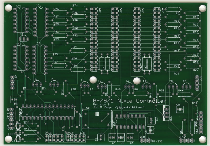
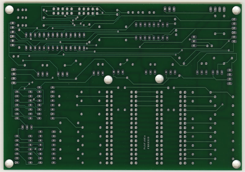
Printed Circuit Boards
PCBFabExpress was used to fabricate seven of the revision 0 boards. There are scans of the boards below. The revision 0 boards contained two errors which were easily remedied by cutting a few traces and soldering in some jumpers. The revision 1 boards schematics and boards have been updated to fix this problem.